Many microscopes record images due to their setup in a tilted manner. Before starting the analysis process the correction of the tilt is crucial. Otherwise large errors will occur in course of the analysis process. The area calculation for instance would accidentally assign data pixels to objects where simply the surrounding structures exhibit apparently similar heights as the objects. Therefore, dotCube supports the scientists with extensive options to correct tilted images precisely and fast.
Read on for getting to know in detail about:
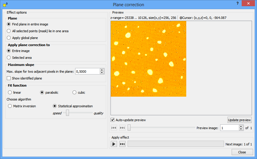
DotCube is able to process the plane detection in three different ways:

Where to apply the plane correction
The plane correction may be applied to a previous marked area or to the whole image. Just select the respective option.

DotCube detects flat regions in scan data by calculating locally the second derivative. Data points which deceed the value specified by "Maximum slope factor" are allocated to a flat region - a plane. Increase or decrease this value to assign more or less data points to the plane.
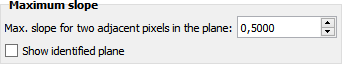
For monitoring the detected plane, select the "Show identified plane" option.
Select the correction algorithm
After detecting a planar region, a three dimensional correction function is applied to the image data in order to remove the tilt. Select the polynomial order (linear, parabolic or cubic) of the tilt distortion to gain the best results.
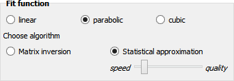
The correction function can be calculated by two algorithms:
The execution of the function may be started by pressing two different shortcut keys:
For more shortcut keys see our detailed list.